AFT Blog
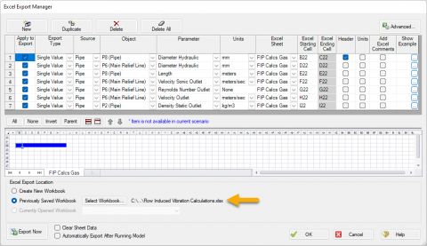
The Opposite of Good Vibrations - Evaluating FIV, AIV, FIP Guidelines from AFT Fathom and AFT Arrow
Learn how to use AFT Fathom and AFT Arrow to help calculate the Likelihood of Failure (LOF) for Flow Induced Vibration (FIV), Acoustic Induced Vibration (AIV), and Flow Induced Pulsation (FIP) in accordance with Energy Institute Guidelines to avoid v...
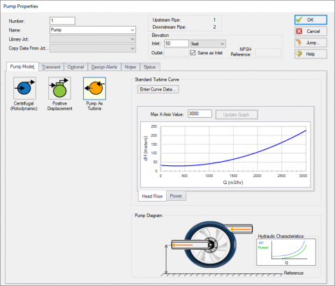
It's a Pump! It's a Turbine! It's a Pump as Turbine!
Pumps and turbines may serve opposite purposes, but fundamentally, they operate under the same principles. Both pieces of equipment convert between usable work and fluid energy, and both often use an impeller to make the conversion. Differences betwe...
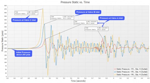
What Is Transient Analysis?
You're tasked to perform a transient analysis of a piping system and it would be really helpful if there was a good software tool out there to help you. Well, you've come to the right place because AFT has great solutions! ...

Know Your Pump & System Curves - Part 3
In the final "Know Your Pump & System Curves" blog series, I am going to discuss the complexities behind pump vs. system curves for systems with pumps in series and parallel configurations. Multiple pumps in series configurations are relatively s...
Digital Twin – Identical or Fraternal?
When I was a child, I was jealous of twins. I thought how cool it would be to have a twin. I had twin cousins a few years older than I was that I saw on a frequent basis. I always got them confused. Which one was Roger, and which one was Ronny? A buz...

That Valve’s Got Character – Applying Pre-defined Characteristic Curves
Valves are often oversimplified during modeling. Understandably, defining a valve with its range of Cv at various open percentages requires much more information than an engineer may have during the initial design phase. However, just like handbook d...
Pulsation in fluid systems...Is it steady-state or is it transient? Well, it is both. Kind of. Pulsation causes periodic transients that are regular in nature and thus considered steady-state. It can be called "steady-state pulsation".
I am not a political commentator. But anyone not living in a cave has to admit that the past year of American politics was just plain wacky. For those of you for whom English is not your first language, "wacky" is a word that basically means (by my personal definition) "strange, highly unusual and a bit crazy". Which also applies to Donald Trump.
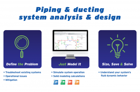
Trying to design and analyze piping systems can be a complicated, and difficult task for engineers. This was especially true before the advent of easily accessible computer technology. Hand calculations required hundreds of hours of painstaking work, by entire teams of people. Great care had to be taken to ensure the reliability and accuracy of the results. Human beings do make mistakes, after all.
In today’s engineering world, there are a multitude of computer tools designed to make the design process simpler, faster, and more reliable, such as AFT’s family of analysis products. AFT products revolve around graphically based, drag and drop interfaces that makes creating a computer model of piping systems quick, and easy. Being able to create simulation models with little effort, however, can be a bit of a double-edged sword.
Frequently in tech support, when a difficult-to-converge model comes in, one of the first things we check is whether or not any tees in the model are being modeled as detailed tees. The reason for this is that the hydraulic calculations involving detailed tees can be complex due to the interdependence between velocity and pressure loss for each pipe connected to the tee. Iteration must, therefore, be performed to find a pressure loss and flow through each connecting pipe that agrees with the rest of the flow and pressure solutions in the model. This begs the question, then, what calculations are...
In AFT Fathom and AFT Impulse, it is possible to model a submerged pump where a short and possibly frictionless suction pipe for the pump’s inlet does not need to be modeled. When modeling a submerged pump, there are two options available for specifying the system inlet boundary condition at the pump suction. As shown in Figure 1 below, the Submerged Pump’s Suction Pressure can either be specified as “Head (HGL)” or “Pressure”. Modeling a submerged pump is not the only time where the “Head (HGL)” or “Pressure” choices will arise. If an Exit Valve (i.e., a valve that discharges...
Yesterday was the 75th anniversary of the Japanese attack on Pearl Harbor which catapulted the United States into World War II. For Americans, there was no way to miss the abundant news coverage and the stories of vets who were there that day and are still alive today to share their experiences. As I read about and watched some of the ceremonies and news it got me thinking about the astounding progress humankind made in the 20th century in the field of aviation.
AFT Fathom can easily generate a pump and system curve for your piping system. Creating a pump and system curve for a simple system with a single flow path and no control features is an easy and typically well-understood process. However, as piping systems are quite complicated with lots of branch points, control features, and dynamic interactions, creating a useful system curve can quickly become a common source of confusion. This three-part blog series is going to help clarify concepts regarding pump and system curves to better understand them. This Part 1 blog will discuss the basics of what pump...