AFT Blog
The Opposite of Good Vibrations - Evaluating FIV, AIV, FIP Guidelines from AFT Fathom and AFT Arrow
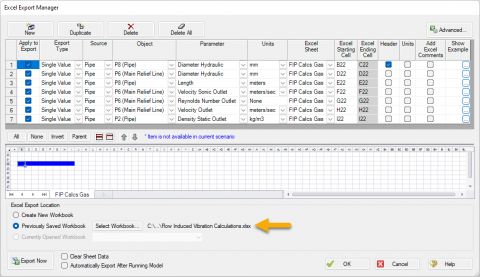
Learn how to use AFT Fathom and AFT Arrow to help calculate the Likelihood of Failure (LOF) for Flow Induced Vibration (FIV), Acoustic Induced Vibration (AIV), and Flow Induced Pulsation (FIP) in accordance with Energy Institute Guidelines to avoid v...
It's a Pump! It's a Turbine! It's a Pump as Turbine!
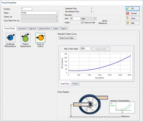
Pumps and turbines may serve opposite purposes, but fundamentally, they operate under the same principles. Both pieces of equipment convert between usable work and fluid energy, and both often use an impeller to make the conversion. Differences betwe...
What Is Transient Analysis?
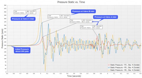
You're tasked to perform a transient analysis of a piping system and it would be really helpful if there was a good software tool out there to help you. Well, you've come to the right place because AFT has great solutions! ...

Know Your Pump & System Curves - Part 3
In the final "Know Your Pump & System Curves" blog series, I am going to discuss the complexities behind pump vs. system curves for systems with pumps in series and parallel configurations. Multiple pumps in series configurations are relatively s...

Digital Twin – Identical or Fraternal?
When I was a child, I was jealous of twins. I thought how cool it would be to have a twin. I had twin cousins a few years older than I was that I saw on a frequent basis. I always got them confused. Which one was Roger, and which one was Ronny? A buz...

That Valve’s Got Character – Applying Pre-defined Characteristic Curves
Valves are often oversimplified during modeling. Understandably, defining a valve with its range of Cv at various open percentages requires much more information than an engineer may have during the initial design phase. However, just like handbook d...
Two years ago this month I wrote this blog article: "Should Engineers Always Perform Waterhammer Analysis of New Pipe Systems?". This was a popular blog. It was written from the fluid dynamic engineer's perspective.
It is possible to model the shell side and tube side of a heat exchanger in AFT Fathom and AFT Arrow where the “hot fluid and cold fluid” circuits can also be included for both sides of a heat exchanger in a single model file! This can be accomplished by creating a "thermal link" between two heat exchangers and using the “Heat Transfer with Energy Balance (Multiple Fluids)” option in the System Properties window.
As shown in Figure 1 below, there are two separate systems modeled on the same Workspace. The left side of the system is an auxiliary cooling water loop while the right side system is the hot oil circulation loop. The two heat exchanger junctions that are highlighted in the red box, J8 and J18, represent the tube side and shell side of a single heat exchanger. The cooling water circuit is on the tube side of the heat exchanger and the hot oil loop is on the shell side of the same heat exchanger. These heat exchanger junctions are “thermally linked” together, as they represent the same physical heat exchanger. Therefore, their resulting heat rates will be the same, but opposite in sign.

An important requirement to keep in mind that will allow the modeling of two sides of a heat exchanger with the “thermal linking” feature is that both fluids on each side of the heat exchanger must remain in fully liquid phase for AFT Fathom (or fully gas phase for AFT Arrow). Therefore, there cannot be any phase change in either fluid circuit or through the heat exchanger itself.
First step is to build a model of the system and include both cooling water and hot oil loops. After all the pipes and junctions are laid out on the Workspace (but not defined), open up the System Properties window and choose the "Heat Transfer with Energy Balance (Multiple Fluids)" option as displayed in Figure 2. A single “default” fluid must be selected and defined. The individual fluids used in each loop will be defined soon.
 option selected. Default fluid is defined.")
Next, the pipes and junctions can be defined with their various thermal models and characteristics (except for the two heat exchanger junctions that will need to be modeled as two sides of one heat exchanger. This will be specified later).
In order to use the "Multiple Fluids" option in System Properties so that two sides of a heat exchanger can be thermally linked, "Fluid Groups" must be created. Before fluids can be assigned to specific “Fluid Groups”, separate groups of all the pipes and junctions in each individual circuit need to be created first.
As shown in Figure 3, select all the pipes and junctions that make up one of the circuits, such as the cooling water loop. Then from the Edit menu, click "Groups", then "Create", and give that group of pipes and junctions that are selected, a name.

Then, select the pipes and junctions that make up the hot oil side. With those objects selected, click "Edit", then "Groups", then "Create" and give the hot oil loop a name.
After two separate groups for each loop have been created, the specific fluids that will be used for each group can now be defined. Click "Edit", then "Groups", then "Fluids". Check both boxes so that both fluid groups can be used.
For the cooling water circuit, click the box with the little dots in the "Fluid" column, then specify the fluid properties, like that in Figure 4. Any of the fluid options are available, except for "User Specified Fluid" (because the "User Specified Fluid" option does not model heat transfer).

Then, specify the fluid properties for the hot oil loop by clicking on its box with the little dots.

After a particular fluid has been chosen for each fluid group, click OK.
Now, the two heat exchangers can be "thermally linked" together.
Open one heat exchanger, and on the Thermal Data tab, specify one of the Effectiveness-NTU thermal models, then check the box to "Link to Heat Exchanger", and select the other heat exchanger from the drop-down menu that you want to link to. Then specify the required parameters. Figure 6 illustrates how to thermally link the cooling water loop tube side with a “Counter-Flow” thermal model and it will link to the Hot Oil Loop heat exchanger.
We have all heard it countless times - "Garbage in, garbage out". As applied to engineering, and specifically to computational engineering software, the admonition is clear - we have to be certain we are properly specifying our engineering input to the software which will compute the behavior we seek to understand.
AFT Arrow solves all of the fundamental controlling equations governing gas dynamics. For more information about which fundamental thermodynamic equations are solved in AFT Arrow, here is an excellent article that discusses gas flow calculations in detail. The "stack effect" is simply one aspect of these equations, and is accounted for by the user input and boundary conditions. Ultimately, flow is driven by pressure difference. The higher you raise a chimney, the lower the atmospheric density and pressure at the discharge. In order to accurately model the "stack effect", the system boundary conditions must be modeled accurately. As the discharge...
Last month AFT concluded its 20th year as a world leading provider of fluid flow simulation software products. A year ago I wrote about AFT's 20th anniversary and the prizes we would be awarding.
Everyone - at least everyone in the USA - is talking about falling oil prices:
Previously, I wrote an article that discussed how to account for density differences between a pump manufacturer's test fluid and a system fluid for pumps as well as the importance, https://www.aft.com/blog/entry/2014/12/02/reference-densities-for-pump-operation. Both AFT Fathom and AFT Impulse can take into account these density differences very easily, thus, reducing the efforts for the user. But what about viscosity corrections? Is it important to take this into account as well? How is this accomplished? Does it really make a difference? If the system fluid you are modeling has a HIGHER VISCOSITY (more resistant to flow) than the fluid the pump was tested with,...